2019年7月10日 星期三

[Robot] 圓形雙層小車底盤組裝(一)

這款圓形小車底盤有一組橡膠輪和一組方向輪,提供較佳的行走穩定性。一般小車底盤只有一層,在安置 Arduino 開發板、馬達驅動板和電池之後,已無多餘空間裝置其他模組,而這組小車底盤有兩層壓克力底板,恰巧可以解決空間不足的問題。


組裝步驟

Step1 撕除壓克力表面保護紙。不撕除也沒關係。

Step2 準備下列材料:

方向輪 *2
M3*12mm 尼龍柱 *8
M3*6mm 螺絲 *8
M3*8mm 螺絲 *8

用 4只 M3*6mm 螺絲將 4支尼龍柱鎖上方向輪,做 2 組下圖組件。


將 2 組方向輪組件各用 4只 M3*8mm 螺絲鎖到底板,如下圖。


這是另一面


Step3 準備下列材料:

M3*30mm 尼龍柱 *4
M3*8mm 螺絲 *4

用 4只 M3*8mm 螺絲將 4支尼龍柱鎖上底板,如下圖。


Step4 準備下列材料:

TT馬達 *2
馬達固定片 *4
M3*30mm 螺絲 *4
M3 螺帽 *4

將 1 只馬達固定片穿過底板,另一只固定片靠著底板側邊,兩片固定板中間夾著馬達,用 2 只 M3*30mm 螺絲穿過固定片和馬達的洞。

提醒您:
1. 雖然此處還沒焊,但建議您在安裝馬達之前,先焊好馬達的電源線。
2. 要注意馬達的方向,也就是齒輪箱的轉軸必須是在底板的十字孔洞那邊。
3. 建議 2 只馬達的電源銅片都朝內,或者是朝外。


用 2 只 M3 螺帽鎖緊。


另一邊的馬達也如法泡製固定。


Step5 準備下列材料:

編碼輪 *2

將 2 只編碼輪小心安裝到馬達轉軸。

提醒您:
1. 如果您沒有紅外線對射模組,此處的編碼輪是可以不必安裝的。
2. 編碼輪最好要移動到十字孔洞的中間,如此才不會與底板產生干涉。


Step6 將 2 只輪胎安裝到馬達轉軸。


Step7 找個地方用螺絲把電池盒固定住。如果底板上沒有適合的孔,需自行鑽孔。


Step8 準備下列材料:

M3*8mm 螺絲 *4

用 4只 M3*8mm 螺絲將上層板鎖到尼龍柱上,如下圖。


Step9 完成,如下圖。


結論

此款小車底盤套件非常容易組裝,但在組裝的過程當中還是有一些細節需要注意,才不會陷入拆拆裝裝的困境。尤其是在加上 Arduino 開發板、馬達驅動板、電池盒、紅外線循跡模組和超音波避障模組等物件後,更應該注意組裝順序,這在下一篇文當中會更加詳細說明。


採購資訊

小車底盤套件 https://goods.ruten.com.tw/item/show?21928032117826


2019年6月21日 星期五

[Arduino] 實做一個文字跑馬燈(二) -- 使用手機發送訊息給 8*32 點陣 LED

在上一個實驗 (https://pizgchen.blogspot.com/2019/06/arduino-led-max7219-832-led.html)
當中文內有提到,可以用 Serial Monitor 視窗輸入文字改變顯示訊息,由此可知應該也可以手機透過藍牙傳送資料來改變顯示的訊息,這樣的話能讓使用者更加方便切換訊息,另一方面也能有更多的應用。本實驗就是修改上一個實驗,讓我們可以用手機來改變顯示的訊息。


在硬體方面,您需要一支智慧型手機、一片藍牙模組和杜邦線4P。HC-05 是具有主從模式的模組,此處我們採用 BT06 藍牙模組,它相容於 HC-06 ,只有"從"模式。有兩點理由讓我們採用 BT06 藍牙模組,一是這個實驗在 Arduino 點陣 LED 這端不需要主動連線手機,因此只需要"從"模式就可以;二是它價錢比 HC-05 便宜。


接線

接續上個實驗,現在把4P杜邦線再接上 BT06 藍牙模組,另一頭如下接法:

Arduino      BT06
Vcc             Vcc
Gnd            Gnd
D8              TXD
D9              RXD

藍牙模組的 STATE 和 EN 針脚可以省略不用。

原始 Software Serial 函式庫裡的範例是接 D10 & D11,這裡之所以改接 D8 & D9 是因為 D10、D11、D13 已被點陣 LED 佔用。

另外,這片藍牙模組的預設參數如下所示:

NAME = BT04-A
BAUD RATE = 9600
PASSWORD = 1234

瞭解這些參數有利於您在手機端的藍牙設定,還有 Arduino 端的程式設定。


Arduino 程式

我們參考了 Software Serial 函式庫裡的範例,把下列幾行程式碼加入上個實驗的程式內:

#include <SoftwareSerial.h>
SoftwareSerial mySerial(8, 9); // RX, TX
mySerial.begin(9600);

並修改函示 readSerial() 部份內容,完整 Arduino 程式碼如下:

#include <SoftwareSerial.h>
#include <MD_Parola.h>
#include <MD_MAX72xx.h>
#include <SPI.h>

// set to 1 if we are implementing the user interface pot, switch, etc
#define USE_UI_CONTROL 0

#if USE_UI_CONTROL
#include <MD_UISwitch.h>
#endif

// Turn on debug statements to the serial output
#define DEBUG 0

#if DEBUG
#define PRINT(s, x) { Serial.print(F(s)); Serial.print(x); }
#define PRINTS(x) Serial.print(F(x))
#define PRINTX(x) Serial.println(x, HEX)
#else
#define PRINT(s, x)
#define PRINTS(x)
#define PRINTX(x)
#endif

// Define the number of devices we have in the chain and the hardware interface
// NOTE: These pin numbers will probably not work with your hardware and may
// need to be adapted
#define HARDWARE_TYPE MD_MAX72XX::PAROLA_HW
#define MAX_DEVICES 4
#define CLK_PIN   13
#define DATA_PIN  11
#define CS_PIN    10

SoftwareSerial mySerial(8, 9); // RX, TX

// HARDWARE SPI
MD_Parola P = MD_Parola(HARDWARE_TYPE, CS_PIN, MAX_DEVICES);
// SOFTWARE SPI
//MD_Parola P = MD_Parola(HARDWARE_TYPE, DATA_PIN, CLK_PIN, CS_PIN, MAX_DEVICES);

// Scrolling parameters
#if USE_UI_CONTROL
const uint8_t SPEED_IN = A5;
const uint8_t DIRECTION_SET = 8;  // change the effect
const uint8_t INVERT_SET = 9;     // change the invert

const uint8_t SPEED_DEADBAND = 5;
#endif // USE_UI_CONTROL

uint8_t scrollSpeed = 25;    // default frame delay value
textEffect_t scrollEffect = PA_SCROLL_LEFT;
textPosition_t scrollAlign = PA_LEFT;
uint16_t scrollPause = 2000; // in milliseconds

// Global message buffers shared by Serial and Scrolling functions
#define BUF_SIZE 75
char curMessage[BUF_SIZE] = { "" };
char newMessage[BUF_SIZE] = { "Robot Wolf Group" };
bool newMessageAvailable = true;

#if USE_UI_CONTROL

MD_UISwitch_Digital uiDirection(DIRECTION_SET);
MD_UISwitch_Digital uiInvert(INVERT_SET);

void doUI(void)
{
  // set the speed if it has changed
  {
    int16_t speed = map(analogRead(SPEED_IN), 0, 1023, 10, 150);

    if ((speed >= ((int16_t)P.getSpeed() + SPEED_DEADBAND)) ||
      (speed <= ((int16_t)P.getSpeed() - SPEED_DEADBAND)))
    {
      P.setSpeed(speed);
      scrollSpeed = speed;
      PRINT("\nChanged speed to ", P.getSpeed());
    }
  }

  if (uiDirection.read() == MD_UISwitch::KEY_PRESS) // SCROLL DIRECTION
  {
    PRINTS("\nChanging scroll direction");
    scrollEffect = (scrollEffect == PA_SCROLL_LEFT ? PA_SCROLL_RIGHT : PA_SCROLL_LEFT);
    P.setTextEffect(scrollEffect, scrollEffect);
    P.displayClear();
    P.displayReset();
  }

  if (uiInvert.read() == MD_UISwitch::KEY_PRESS)  // INVERT MODE
  {
    PRINTS("\nChanging invert mode");
    P.setInvert(!P.getInvert());
  }
}
#endif // USE_UI_CONTROL

void readSerial(void)
{
  static char *cp = newMessage;

  while (mySerial.available())
  {
    *cp = (char)mySerial.read();
    if ((*cp == '\n') || (cp - newMessage >= BUF_SIZE-2)) // end of message character or full buffer
    {
      *cp = '\0'; // end the string
      // restart the index for next filling spree and flag we have a message waiting
      cp = newMessage;
      newMessageAvailable = true;
    }
    else  // move char pointer to next position
      cp++;
  }
}

void setup()
{
  Serial.begin(57600);
  Serial.print("\n[Parola Scrolling Display]\nType a message for the scrolling display\nEnd message line with a newline");

  mySerial.begin(9600);
  mySerial.println("Robot Wolf Group -- LED Matrix");
  
#if USE_UI_CONTROL
  uiDirection.begin();
  uiInvert.begin();
  pinMode(SPEED_IN, INPUT);

  doUI();
#endif // USE_UI_CONTROL

  P.begin();
  P.displayText(curMessage, scrollAlign, scrollSpeed, scrollPause, scrollEffect, scrollEffect);
}

void loop()
{
#if USE_UI_CONTROL
  doUI();
#endif // USE_UI_CONTROL

  if (P.displayAnimate())
  {
    if (newMessageAvailable)
    {
      strcpy(curMessage, newMessage);
      newMessageAvailable = false;
    }
    P.displayReset();
  }
  
  readSerial(); 
  
}


手機 APP

下載並安裝手機 APP (Android) 

https://www.dropbox.com/s/fe3vuxl7d1w0bk8/LED_Matrix.apk?dl=0

開啟 APP 後會先出現要求您啟用藍牙設備的訊息,您同意後再選擇要連線的藍牙裝置,然後會出現下列畫面:


點按 [Connect] 鈕連線藍牙,連線後在 Display 文字欄內輸入文字,按下 [Send] 鈕就可以改變點陣 LED 上的訊息。

在 [Send] 鈕下方有三個按鈕,按下後會直接把預設好的訊息傳出,
[<<<] 鈕會傳出 "<<<",這可以代表自行車的左轉燈;
[>>>] 鈕會傳出 ">>>",這可以代表自行車的右轉燈;
[STOP] 鈕會傳出 "STOP",這可以代表自行車的煞車燈。


結論

由於點陣 LED 目前的動態顯示方式是由右而左捲動文字,在操作過程當中可以感覺到左右轉燈和煞車燈顯示的方式並非是我們所想要的。其實,原始程式預留多種動態顯示方式,這部份我們留待下回再來做個探討。


延伸資料

Arduino bluetooth controled 8*32 LED Matrix https://electronoobs.com/eng_arduino_tut14.php


採購資訊


2019年6月17日 星期一

[Arduino] 實做一個文字跑馬燈(一) -- 使用 MAX7219 驅動 8*32 點陣 LED


本實驗是做一個 8*32 點陣文字跑馬燈,如果只使用 Arduino Uno 本身的腳位,是很難點亮 8*32 點陣 LED,我們藉由使用 MAX7219 IC 就可以輕易解決這個問題。

一顆 MAX7219 IC 剛好可以驅動一只 8*8 點陣 LED,因此要驅動 8*32 點陣 LED 需要 4 顆 MAX7219 IC 串接起來。

市面上有現成的 8*32 點陣 LED 模組,如下圖


在開始實驗之前,建議您最好先了解一下 MAX7219
Datasheet http://images.100y.com.tw/pdf_file/35-MAXIM-MAX7219.pdf


接線

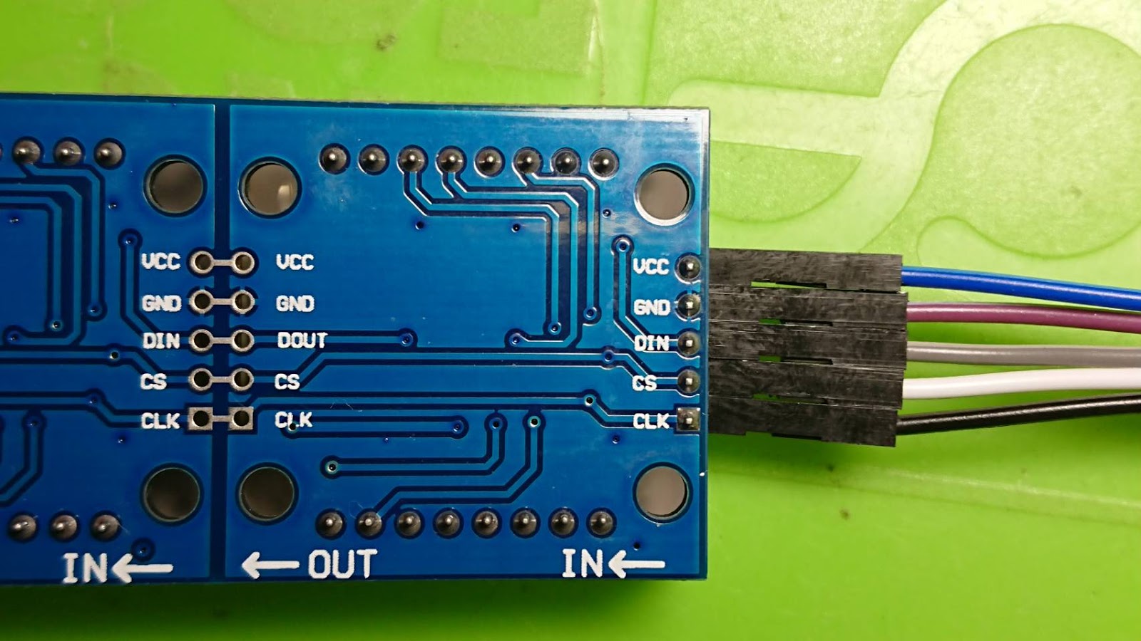
把 5P杜邦線一頭接上點陣 LED,這是正面


這是背面


請注意 IN / OUT 方向。

把 5P杜邦線另一頭接上 Arduino,接線如下


Arduino      LED Matrix
Vcc             Vcc
Gnd            Gnd
P10             CS
P11             DIN
P13             CLK


Arduino程式

程式碼 

#include <MD_Parola.h>
#include <MD_MAX72xx.h>
#include <SPI.h>

// set to 1 if we are implementing the user interface pot, switch, etc
#define USE_UI_CONTROL 0

#if USE_UI_CONTROL
#include <MD_UISwitch.h>
#endif

// Turn on debug statements to the serial output
#define DEBUG 0

#if DEBUG
#define PRINT(s, x) { Serial.print(F(s)); Serial.print(x); }
#define PRINTS(x) Serial.print(F(x))
#define PRINTX(x) Serial.println(x, HEX)
#else
#define PRINT(s, x)
#define PRINTS(x)
#define PRINTX(x)
#endif

// Define the number of devices we have in the chain and the hardware interface
// NOTE: These pin numbers will probably not work with your hardware and may
// need to be adapted
#define HARDWARE_TYPE MD_MAX72XX::PAROLA_HW
#define MAX_DEVICES 4
#define CLK_PIN   13
#define DATA_PIN  11
#define CS_PIN    10

// HARDWARE SPI
MD_Parola P = MD_Parola(HARDWARE_TYPE, CS_PIN, MAX_DEVICES);
// SOFTWARE SPI
//MD_Parola P = MD_Parola(HARDWARE_TYPE, DATA_PIN, CLK_PIN, CS_PIN, MAX_DEVICES);

// Scrolling parameters
#if USE_UI_CONTROL
const uint8_t SPEED_IN = A5;
const uint8_t DIRECTION_SET = 8;  // change the effect
const uint8_t INVERT_SET = 9;     // change the invert

const uint8_t SPEED_DEADBAND = 5;
#endif // USE_UI_CONTROL

uint8_t scrollSpeed = 25;    // default frame delay value
textEffect_t scrollEffect = PA_SCROLL_LEFT;
textPosition_t scrollAlign = PA_LEFT;
uint16_t scrollPause = 2000; // in milliseconds

// Global message buffers shared by Serial and Scrolling functions
#define BUF_SIZE 75
char curMessage[BUF_SIZE] = { "" };
char newMessage[BUF_SIZE] = { "Hello! Enter new message?" };
bool newMessageAvailable = true;

#if USE_UI_CONTROL

MD_UISwitch_Digital uiDirection(DIRECTION_SET);
MD_UISwitch_Digital uiInvert(INVERT_SET);

void doUI(void)
{
  // set the speed if it has changed
  {
    int16_t speed = map(analogRead(SPEED_IN), 0, 1023, 10, 150);

    if ((speed >= ((int16_t)P.getSpeed() + SPEED_DEADBAND)) ||
      (speed <= ((int16_t)P.getSpeed() - SPEED_DEADBAND)))
    {
      P.setSpeed(speed);
      scrollSpeed = speed;
      PRINT("\nChanged speed to ", P.getSpeed());
    }
  }

  if (uiDirection.read() == MD_UISwitch::KEY_PRESS) // SCROLL DIRECTION
  {
    PRINTS("\nChanging scroll direction");
    scrollEffect = (scrollEffect == PA_SCROLL_LEFT ? PA_SCROLL_RIGHT : PA_SCROLL_LEFT);
    P.setTextEffect(scrollEffect, scrollEffect);
    P.displayClear();
    P.displayReset();
  }

  if (uiInvert.read() == MD_UISwitch::KEY_PRESS)  // INVERT MODE
  {
    PRINTS("\nChanging invert mode");
    P.setInvert(!P.getInvert());
  }
}
#endif // USE_UI_CONTROL

void readSerial(void)
{
  static char *cp = newMessage;

  while (Serial.available())
  {
    *cp = (char)Serial.read();
    if ((*cp == '\n') || (cp - newMessage >= BUF_SIZE-2)) // end of message character or full buffer
    {
      *cp = '\0'; // end the string
      // restart the index for next filling spree and flag we have a message waiting
      cp = newMessage;
      newMessageAvailable = true;
    }
    else  // move char pointer to next position
      cp++;
  }
}

void setup()
{
  Serial.begin(57600);
  Serial.print("\n[Parola Scrolling Display]\nType a message for the scrolling display\nEnd message line with a newline");

#if USE_UI_CONTROL
  uiDirection.begin();
  uiInvert.begin();
  pinMode(SPEED_IN, INPUT);

  doUI();
#endif // USE_UI_CONTROL

  P.begin();
  P.displayText(curMessage, scrollAlign, scrollSpeed, scrollPause, scrollEffect, scrollEffect);
}

void loop()
{
#if USE_UI_CONTROL
  doUI();
#endif // USE_UI_CONTROL

  if (P.displayAnimate())
  {
    if (newMessageAvailable)
    {
      strcpy(curMessage, newMessage);
      newMessageAvailable = false;
    }
    P.displayReset();
  }
  readSerial();
}

上電後,初始文字會顯示捲動的「Hello! Enter new Message?」。
您可以打開 Serial Monitor,將鮑率調到 57600,在上方的欄位輸入新的文字並按下 <Enter> 鍵,就可以顯示新的文字。

初始顯示

叫出 Serial Monitor

輸入新文字

來看一下影片


進階項目

1. 建議您可以將本實驗改成手機藍芽連線,動態變更文字內容和顯示方式。

2. 除了顯示文字之外,最好也可以顯示圖案,可以是靜態圖案,最好是動態圖案。當然如果您功力夠好的話,最好是可以在手機上建立多幅影格形成一幅動畫,再透過藍芽立即傳給 Arduino 讓點陣 LED 顯示。


延伸資料

實做一個文字跑馬燈(二) -- 用手機傳送訊息給點陣 LED https://pizgchen.blogspot.com/2019/06/arduino-led-832-led.html


採購資訊

8*32 點陣LED模組 https://goods.ruten.com.tw/item/show?21922556868059


2019年3月10日 星期日

[Arduino] 實做 PCF8574 模組的輸出入功能(二)

本文在說明前文提到可以串聯多個 PCF8574 模組作為多個輸出入端口,這裏只實做 2 個模組串聯。模組端部留有公排針與母排針,串聯時只要將公排針插入母排針即可,記得還需要調整跳線帽重新定址,如下圖。


如果您對 PCF8574 模組還不熟悉,建議您先參閱
「實做 PCF8574 模組的輸出入功能(一)」 http://pizgchen.blogspot.com/2019/03/arduino-pcf8574.html


接線

Arduino       PCF8574 模組
VCC            VCC
GND           GND
A4               SDA
A5               SCL

將 2 個 PCF8574 模組串接,並調整第二個模組的跳線帽,第一個模組的位址是 0x38,第二個模組的位址是 0x39,如下圖。

第一個模組

第二個模組

兩個模組串接


實作範例一

這個實驗用 Arduino 讓第一個模組的 pin0 腳位和第二個模組的 pin7 腳位 LED 每秒閃一次,所以您還應該在那 2 個腳位設置 LED 電路,然後您可以看到閃爍的 LED,並在 Arduino 的序列視窗看到腳位的輸出狀態。

程式碼

#include "HCPCF8574.h"      //Include the HCPCF8574 library

#define I2C_ADD1 0x38       //I2C address of the first PCF8574 device
#define I2C_ADD2 0x39       //I2C address of the second PCF8574 device

HCPCF8574 Port1(I2C_ADD1);  //Create an instance of the library to control the first device
HCPCF8574 Port2(I2C_ADD2);  //Create an instance of the library to control the second device

void setup()
{
  Serial.begin(9600);
  Port1.init();             //Initiliase the first PCF8574 (all pins are set to high)
  Port2.init();             //Initiliase the second PCF8574 (all pins are set to high)
  Port1.pinMode(0, OUTPUT); //Set digital pin 0 on the first device to an output
  Port2.pinMode(7, OUTPUT); //Set digital pin 7 on the second device to an output
}


void loop()
{
  Serial.println("Port1 pin0 & Port2 pin7 is HIGH");
  Port1.pinWrite(0, HIGH);  //Set digital pin 0 on the first device high
  Port2.pinWrite(7, HIGH);  //Set digital pin 7 on the second device high
  delay(1000);                       //Wait 1 second

  Serial.println("Port1 pin0 & Port2 pin7 is LOW");
  Port1.pinWrite(0, LOW);   //Set digital pin 0 on the first device low
  Port2.pinWrite(7, LOW);   //Set digital pin 7 on the second device low
  delay(1000);                       //Wait another second
}


實作範例二

這個實驗用 Arduino 讀取 2 組 PCF8574AT 模塊的 P0~P7 腳位信號,所以您還應該在那些腳位總共設置 16 個按鈕電路,然後可以在 Arduino 的序列視窗顯示按鈕的開關狀態。

程式碼

#include "HCPCF8574.h"      //Include the HCPCF8574 library

#define I2C_ADD1 0x38       //I2C address of the first PCF8574 device
#define I2C_ADD2 0x39       //I2C address of the second PCF8574 device

HCPCF8574 Port1(I2C_ADD1);  //Create an instance of the library to control the first device
HCPCF8574 Port2(I2C_ADD2);  //Create an instance of the library to control the second device

void setup()
{
  Serial.begin(9600);
  Port1.init();             //Initiliase the first PCF8574 (all pins are set to high)
  Port2.init();             //Initiliase the second PCF8574 (all pins are set to high)
  for (int i=0; i<8 ; i++) {
    Port1.pinMode(i, INTPUT); //Set digital pin 0 on the first device to an output
    Port2.pinMode(i, INTPUT); //Set digital pin 7 on the second device to an output
  }
}

void loop()
{
   boolean State10 = Port1.pinRead(0);  //Read the port1 of digital pin 0
   boolean State11 = Port1.pinRead(1);  //Read the port1 of digital pin 1
   boolean State12 = Port1.pinRead(2);  //Read the port1 of digital pin 2
   boolean State13 = Port1.pinRead(3);  //Read the port1 of digital pin 3
   boolean State14 = Port1.pinRead(4);  //Read the port1 of digital pin 4
   boolean State15 = Port1.pinRead(5);  //Read the port1 of digital pin 5
   boolean State16 = Port1.pinRead(6);  //Read the port1 of digital pin 6
   boolean State17 = Port1.pinRead(7);  //Read the port1 of digital pin 7

   boolean State20 = Port2.pinRead(0);  //Read the port2 of digital pin 0
   boolean State21 = Port2.pinRead(1);  //Read the port2 of digital pin 1
   boolean State22 = Port2.pinRead(2);  //Read the port2 of digital pin 2
   boolean State23 = Port2.pinRead(3);  //Read the port2 of digital pin 3
   boolean State24 = Port2.pinRead(4);  //Read the port2 of digital pin 4
   boolean State25 = Port2.pinRead(5);  //Read the port2 of digital pin 5
   boolean State26 = Port2.pinRead(6);  //Read the port2 of digital pin 6
   boolean State27 = Port2.pinRead(7);  //Read the port2 of digital pin 7

   Serial.println("Port1="); 
   Serial.print(State10); Serial.print(State11); Serial.print(State12);   Serial.print(State13);
   Serial.print(State14); Serial.print(State15); Serial.print(State16);   Serial.print(State17);

   Serial.println("Port2="); 
   Serial.print(State20); Serial.print(State21); Serial.print(State22);   Serial.print(State23);
   Serial.print(State24); Serial.print(State25); Serial.print(State26);   Serial.print(State27);
   
   delay(1000);                       //Wait another second
}


採購資訊

PCF8574AT I/O擴展模塊 https://goods.ruten.com.tw/item/show?21908917689628


2019年3月3日 星期日

[Arduino] 實做 PCF8574 模組的輸出入功能(一)


此模組採用 PCF8574AT 芯片,具有 8 位輸入/輸出 (I/O) 擴展功能,您可以通過串行 I2C 接口擴展微控制器的可用數字 I/O 引腳。該器件具有8位準雙向 I/O 端口 (P0~P7),包括具有高電流驅動能力的鎖存輸出,可直接驅動LED。每個準雙向 I/O 都可以用作輸入或輸出,而無需使用數據方向控制信號。

3個板載跳線允許選擇最多8個 I2C 地址,這意味著最多 8 個模組 (64個 I/O 引腳) 可以連接到同一個 I2C 接口。該模組的每一端還具有方便的輸入和輸出接頭,因此可以簡單地以菊花鏈形式連接其他模塊,而無需額外的電線等。

註:模組附帶 PCF8574T 或 PCF8574AT 芯片,它會有不同的 I2C 地址,範圍如下:

PCF8574T = 0x20至0x27
PCF8574AT = 0x38至0x3F

PCF8574AT 模組 VCC工作電壓為 2.5~6V,低待機最大電流消耗 10μA,具有漏極開路中斷輸出功能,並與 Arduino 等大多數微控制器兼容,具有高電流驅動能力的鎖存輸出,閂鎖性能超過每 JESD 78 100 mA,Class II 。


Datasheet http://pdf1.alldatasheet.com/datasheet-pdf/view/18216/PHILIPS/PCF8574AT.html


接線

Arduino        PCF8574AT 模組
VCC             VCC
GND            GND
A4                SDA
A5                SCL


實作範例一

這個實驗用 Arduino 讀取 PCF8574AT 模組的 P0 腳位信號,所以您還應該在該腳位設置一個按鈕電路,然後在 Arduino 的序列視窗顯示按鈕的開關狀態。

程式碼

#include "HCPCF8574.h"    //Include the HCPCF8574 library

#define I2C_ADD 0x38      //I2C address of the PCF8574

HCPCF8574 Port(I2C_ADD);  //Create an instance of the library

void setup()
{
  Serial.begin(9600);     //Initiliase the Arduino serial library.
  Port.init();            //Initiliase the PCF8574 (all pins are set to high)
  Port.pinMode(0, INPUT); //Set digital pin 0 to an input
}

void loop()
{
  boolean State = Port.pinRead(0);  //Read the state of digital pin 0
  // Output the state to the serial port
  Serial.print("Pin 0 = ");
  if(State)
    Serial.println("HIGH");
  else
    Serial.println("LOW");

  delay(100);
}


實作範例二

承上個實驗一樣用 Arduino 讀取 PCF8574AT 模塊的 P0 腳位信號(您仍應該在該腳位設置一個按鈕電路),然後用 PCF8574AT 模塊的 P1 腳位讓 LED 隨著按鈕開關明滅(您應該在該腳位串接一個 LED 電路)。

程式碼

#include "HCPCF8574.h"    //Include the HCPCF8574 library

#define I2C_ADD 0x38      //I2C address of the PCF8574

HCPCF8574 Port(I2C_ADD);  //Create an instance of the library

void setup()
{
  Serial.begin(9600);     //Initiliase the Arduino serial library.
  Port.init();            //Initiliase the PCF8574 (all pins are set to high)
  Port.pinMode(0, INPUT); //Set digital pin 0 to an input
  Port.pinMode(1, OUTPUT); //Set digital pin 1 to an output
}

void loop()
{
  boolean State = Port.pinRead(0);  //Read the state of digital pin 0
  // Output the state to the serial port
  // Serial.print("Pin 0 = ");
  if(State)
    // Serial.println("HIGH");
    Port.pinWrite(1, HIGH);
  else
    // Serial.println("LOW");
    Port.pinWrite(1, LOW);

  delay(100);
}


後記

1.上電後的 PCF8574 模組腳位作為輸出時,是在 HIGH 的狀態,這個需要注意一下。

2.在 PCF8574 模組腳位作為輸出時,發現串接限流電阻 220R 的白發紅 5mm LED 並不是很亮,移除限流電阻後也沒達到正常亮度,如果真要用它來點亮 LED,應加裝電晶體來驅動 LED。


相關連結

實做 PCF8574 模組的輸出入功能(二) https://pizgchen.blogspot.com/2019/03/arduino-pcf8574_10.html


採購資訊

PCF8574AT I/O擴展模塊 https://goods.ruten.com.tw/item/show?21908917689628


2018年12月7日 星期五

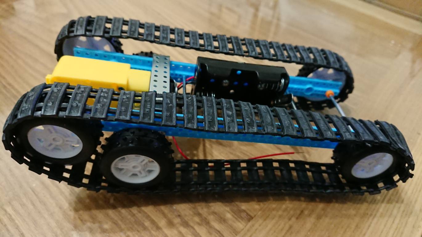
[Robot] 履帶車(坦克車)底盤套件組裝

這一款履帶車(坦克車)底盤套件雖然價格低廉,但它搭載的減速馬達卻是動力十足,就是再崎嶇不平的地形也可輕易越過。
底盤套件


工具

1.烙鐵
2.焊錫
3.尖嘴鉗
4.斜口鉗
5.M2 螺絲起子


組裝步驟

Step1 使用烙鐵和焊錫將電池盒電線焊到馬達上。


Step2 用 2 只螺絲先把電池盒鎖到塑膠條,再拿出 2 支中間長度的鐵條插上塑膠條。

提醒您:
1. 須注意電池盒和鐵條在塑膠條上的位置。
2. 塑膠條中間孔有通孔和未通孔兩種,鐵條要插到未通孔上。這部份要插緊避免鬆脫,如果鐵條插不進塑膠條,可用鐵鎚或重物將其敲進。


Step3 將 2 支鐵條的另一端也插上塑膠條。


Stpe4 使用 2 只螺絲將 2 片長 L 形鐵片鎖到塑膠條。
提醒您:須注意 L 形鐵片在塑膠條上的位置。


Step5 使用 2 只螺絲將 2 片短 L 形鐵片鎖到塑膠條。


Step6 將 2 支最短的鐵條穿過桔色固定環備用。


Step7 馬達置放在兩支塑膠條中間 (由於固定馬達這端是履帶車頭,此時要注意馬達轉動的方向),馬達的鐵殼有磁性,他會吸住長 L 形鐵片,再將 2 支短鐵條分別穿過塑膠條插進馬達軸心。

提醒您:須注意馬達軸心在塑膠條上的位置。


將最長 2 支鐵條先穿過 2 只桔色固定環,一支穿過車尾塑膠條中間通孔,另一支穿過短 L 形鐵片。


Steo7 調整桔色固定環位置,使 2 支鐵條平均置中,而且保持鬆緊適中地可以轉動。


Step8 裝上 6 只輪子。調整這 3 對子使其保持同樣寬度。


Step9 裝上履帶,至此完成。


這是車頭細部

這是車尾細部

這是電池盒細部


觀賞影片


採購資訊

履帶車(坦克車)底盤套件 https://goods.ruten.com.tw/item/show?21849173965858